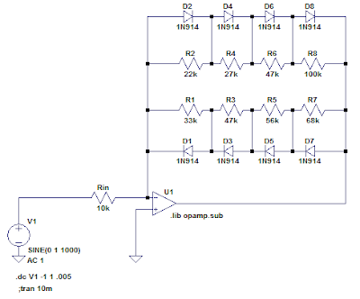
Whereas the Dogzilla circuit took a big input signal and used the diode ladder to sequentially switch in a group of resistors in parallel on the bottom of an attenuator, I used the diode ladder in an operational amplifier's feedback loop to sequentially short out resistors in series, thus decreasing gain for greater output signals. Here's the basic configuration, with an ideal op amp:
When the output voltage is near 0, all four diode pairs are effectively open circuits, so the gain is determined by: A = - (R1 + R2 + R3 + R4) / Rin
As the output voltage increases in magnitude, the voltage across the largest resistor (in this case R4) will be the first to reach a diode forward drop, at which point D7 or D8 (depending on polarity) will turn on and the gain after that point is reduced to: A = - (R1 + R2 + R3) / Rin
This continues with further increases in output voltage, turning off the resistors from larger to smaller until the feedback resistance is effectively determined only by the series dynamic forward resistances of the diode string, about 2 kΩ under these conditions.
In practice, real diodes will switch on gradually, with all four transitions overlapping somewhat. The transfer function looks like this:
Here is the output (green) in response to an increasing sine wave input (blue):
A few notes on this circuit (some may be obvious to you):
- To make a true soft clipper à la Nachbaur, there would be an additional resistor in the series string, with no corresponding diode pair bypassing it. I omitted this resistor because I wanted the output to be strictly limited by the series voltage drop across all diodes. This avoids the possibility of driving the op amp too close to its rails. (Intentional clipping with diodes = good; unintentional clipping by the op amp = bad.)
- I chose an inverting amplifier configuration because the non-inverting arrangement must have a gain of at least 1. I needed the circuit to act as an attenuator for the largest input signals to cause the hard limit behavior described above.
- You can shuffle the resistors around without changing the behavior. The diodes will always turn on in descending order of their associated resistor value.
- The ratio of the gains from maximum to minimum (before hard clipping) must be greater than the number of diode pairs. To see why, consider the case with 4 resistors, with minimum resistance R1 and having a total series resistance of 4×R1 (thus setting the gain ratio to 4) the result is a degenerate case where all resistors are equal and all diodes in each direction turn on simultaneously. In order to have the diodes turn on squentially, the resistor values must increase (at least infinitessimally).
- Because the transfer function is symmetrical, only odd harmonic distortion is introduced. There are a few simple ways to introduce asymmetry, and therefore add some even harmonics.
I came up with a couple spreadsheets to help select resistors for the ladder. Each starts with the same inputs: Total resistance of the string, input resistance, gain reduction ratio, and number of diode steps in the string. Here are links (on Google Sheets) to the spreadsheets; you can copy to your own Google Drive to edit:
Each has a minimum required gain ratio in order to get meaningful values for the resistors. For Calculator 1, the ratio must be greater than the number of diode steps (see note 4 above). For Calculator 2, the ratio must be greater than 2n-1.
Here is the simplest way to introduce asymmetry: Use two different strings of resistors, each with diodes of only one polarity. The effective total resistance (which sets maximum gain) is the parallel combination of both series strings:
- Calculator 1 (quadratic gain change). This uses a linear change in individual resistors which leads to a quadratic gain reduction function by step. This has a more gradual reduction from full gain (around the zero crossing), but a harder transition to full clipping at higher outputs.
- Calculator 2 (geometric gain change). This uses a geometric change in individual resistors, which has a more quick reduction from highest gains , but a more gradual transition to full clipping.
Each has a minimum required gain ratio in order to get meaningful values for the resistors. For Calculator 1, the ratio must be greater than the number of diode steps (see note 4 above). For Calculator 2, the ratio must be greater than 2n-1.
Here is the simplest way to introduce asymmetry: Use two different strings of resistors, each with diodes of only one polarity. The effective total resistance (which sets maximum gain) is the parallel combination of both series strings:
The change in the transfer function is subtle:
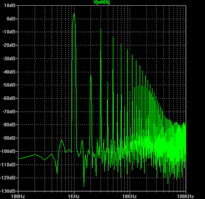
But a Fourier analysis (based here on 1 kHz sine input) shows some addition of even harmonics:
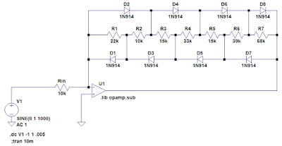
If you want to use fewer resistors, you could stagger the interconnections like this:
You could also modify any of the above with an unequal number of diodes in each polarity. This simple example:
Has a more obvious asymmetry in its transfer function:
And somewhat more pronounced even harmonics:
For my first test, I breadboarded the following variant of the circuit:
A few notes on this circuit:
A few notes on this circuit:
- I used a TL082CP dual op amp that I had on hand. It has a unity-gain bandwidth of 3 MHz and a slew rate of 13 V/µs. Both of these end up being important, which is why I couldn't make use of the LM324 (1 MHz & 0.5 V/µs) that I also had on hand, which would have been better suited to single-ended battery power supply.
- Resistor and capacitor values were chosen from what I had on hand.
- The resistor/diode ladder was designed for 20:1 gain reduction before hard clipping. I used both calculator spreadsheets above, one for the positive half and one for the negative half. (Rather than using the resistor values directly, I had to compare the cumulative resistances and select incremental values to build up to the required totals.)
Here is a brief sound sample, playing a Yamaha RGZ211M (with various pickup & control settings) through the circuit, recorded direct to my audio interface:
Initial thoughts and impressions:
Initial thoughts and impressions:
- Since there was no tone shaping included in the circuit, it suffers from high-end fizz and the low end tends to swamp the distortion at high gain. Not a surprise. It probably needs a pre-emphasis/de-emphasis network to kill the bass before the distortion is applied, and a low pass to clean up the fizz.
- Since there was no gain control, the guitar's volume must be used. Over most of the adjustment range, the apparent loudness does not change much, only the color. Only at the low end of the range is apparent volume affected.
- It's noisy, especially with single-coil pickups. Considering that it has a gain of about 46 dB for the quietest signals, I guess that's to be expected. A noise gate is probably in order.


