Showing posts with label nachbaur. Show all posts

Sunday, May 31, 2015

An Op Amp & Diode Ladder Clipper

My recent series of posts about Fred Nachbaur's “Dogzilla” diode limiter was written because I was considering using a variant of that circuit in a forthcoming project. In the end, I realized Fred's circuit would not be suitable due to the high input voltage swing required to really make it effective.  I did come up with a soft clipper circuit using a diode ladder that would still work within a lower operating voltage range, which I will describe in this post.

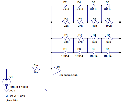
Whereas the Dogzilla circuit took a big input signal and used the diode ladder to sequentially switch in a group of resistors in parallel on the bottom of an attenuator, I used the diode ladder in an operational amplifier's feedback loop to sequentially short out resistors in series, thus decreasing gain for greater output signals. Here's the basic configuration, with an ideal op amp:

When the output voltage is near 0, all four diode pairs are effectively open circuits, so the gain is determined by: A = - (R1 + R2 + R3 + R4) / Rin

As the output voltage increases in magnitude, the voltage across the largest resistor (in this case R4) will be the first to reach a diode forward drop, at which point D7 or D8 (depending on polarity) will turn on and the gain after that point is reduced to: A = - (R1 + R2 + R3) / Rin

This continues with further increases in output voltage, turning off the resistors from larger to smaller until the feedback resistance is effectively determined only by the series dynamic forward resistances of the diode string, about 2 kΩ under these conditions.

In practice, real diodes will switch on gradually, with all four transitions overlapping somewhat.  The transfer function looks like this:


Here are the currents flowing through diodes D2 (magenta), D4 (green), D6 (blue) and D8 (red) over the same range of input voltage.  (The odd-numbered diodes pick up the negative half of the input cycle):


Here are the voltages across R1 (magenta), R2 (red), R3 (blue) and R4 (green) for that same input:


Here is the output (green) in response to an increasing sine wave input (blue):


A few notes on this circuit (some may be obvious to you):

  1. To make a true soft clipper à la Nachbaur, there would be an additional resistor in the series string, with no corresponding diode pair bypassing it.  I omitted this resistor because I wanted the output to be strictly limited by the series voltage drop across all diodes.  This avoids the possibility of driving the op amp too close to its rails.  (Intentional clipping with diodes = good; unintentional clipping by the op amp = bad.)
  2. I chose an inverting amplifier configuration because the non-inverting arrangement must have a gain of at least 1.  I needed the circuit to act as an attenuator for the largest input signals to cause the hard limit behavior described above.
  3. You can shuffle the resistors around without changing the behavior.  The diodes will always turn on in descending order of their associated resistor value.
  4. The ratio of the gains from maximum to minimum (before hard clipping) must be greater than the number of diode pairs. To see why, consider the case with 4 resistors, with minimum resistance R1 and having a total series resistance of 4×R1 (thus setting the gain ratio to 4) the result is a degenerate case where all resistors are equal and all diodes in each direction turn on simultaneously. In order to have the diodes turn on squentially, the resistor values must increase (at least infinitessimally).
  5. Because the transfer function is symmetrical, only odd harmonic distortion is introduced. There are a few simple ways to introduce asymmetry, and therefore add some even harmonics.
I came up with a couple spreadsheets to help select resistors for the ladder.  Each starts with the same inputs: Total resistance of the string, input resistance, gain reduction ratio, and number of diode steps in the string. Here are links (on Google Sheets) to the spreadsheets; you can copy to your own Google Drive to edit:

  • Calculator 1 (quadratic gain change). This uses a linear change in individual resistors which leads to a quadratic gain reduction function by step.  This has a more gradual reduction from full gain (around the zero crossing), but a harder transition to full clipping at higher outputs.
  • Calculator 2 (geometric gain change). This uses a geometric change in individual resistors, which has a more quick reduction from highest gains , but a more gradual transition to full clipping.

Each has a minimum required gain ratio in order to get meaningful values for the resistors.  For Calculator 1, the ratio must be greater than the number of diode steps (see note 4 above).  For Calculator 2, the ratio must be greater than 2n-1.

Here is the simplest way to introduce asymmetry: Use two different strings of resistors, each with diodes of only one polarity.  The effective total resistance (which sets maximum gain) is the parallel combination of both series strings:
The change in the transfer function is subtle:


But a Fourier analysis (based here on 1 kHz sine input) shows some addition of even harmonics:


If you want to use fewer resistors, you could stagger the interconnections like this:


You could also modify any of the above with an unequal number of diodes in each polarity. This simple example:


Has a more obvious asymmetry in its transfer function:
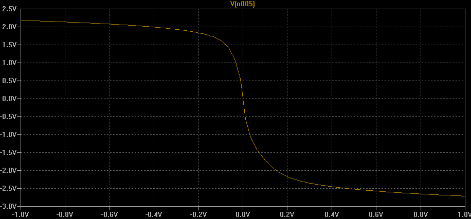

And somewhat more pronounced even harmonics:


For my first test, I breadboarded the following variant of the circuit:


A few notes on this circuit:
  • I used a TL082CP dual op amp that I had on hand. It has a unity-gain bandwidth of 3 MHz and a slew rate of 13 V/µs.  Both of these end up being important, which is why I couldn't make use of the LM324 (1 MHz & 0.5 V/µs) that I also had on hand, which would have been better suited to single-ended battery power supply.
  • Resistor and capacitor values were chosen from what I had on hand.
  • The resistor/diode ladder was designed for 20:1 gain reduction before hard clipping. I used both calculator spreadsheets above, one for the positive half and one for the negative half. (Rather than using the resistor values directly, I had to compare the cumulative resistances and select incremental values to build up to the required totals.)
Here is a brief sound sample, playing a Yamaha RGZ211M (with various pickup & control settings) through the circuit, recorded direct to my audio interface:

Initial thoughts and impressions:
  • Since there was no tone shaping included in the circuit, it suffers from high-end fizz and the low end tends to swamp the distortion at high gain.  Not a surprise.  It probably needs a pre-emphasis/de-emphasis network to kill the bass before the distortion is applied, and a low pass to clean up the fizz.
  • Since there was no gain control, the guitar's volume must be used.  Over most of the adjustment range, the apparent loudness does not change much, only the color.  Only at the low end of the range is apparent volume affected.
  • It's noisy, especially with single-coil pickups.  Considering that it has a gain of about 46 dB for the quietest signals, I guess that's to be expected.  A noise gate is probably in order.


Sunday, May 3, 2015

The Nachbaur Diode Limiter, Part 3: Other variations

This post is part three in a series of three.
Part one discussed the basics.
Part two discussed transfer function shapes and resistor selection.

Listening Test

I ran a test of the Nachbaur Diode Limiter as a passive outboard effect.  The aux sends on my audio interface can drive about 8.18 V peak.  I breadboarded a 4-stage version like this:

Resistors were selected using my spreadsheet to have a final knee voltage of 8 V, and a final attenuation 10 (gain of 0.1).


Below are the audible results.  The program consists of a test tone and a DI-recording of my Danelectro 63 baritone guitar:
  1. 5 seconds of 1 kHz sine wave, increasing linearly in amplitude from 0 to full scale.
  2. A simple chord pattern.
  3. A simple single-note lead.
Each guitar section is normalized to full scale in order to just hit the last knee of the limiter.  The program is repeated for each of the following:
  1. Dry sound
  2. Through the limiter.
  3. Through a 160 Hz 1st-order highpass, normalized, and then through the limiter. (This was skipped for the 1 kHz test tone).
  4. Through the limiter, re-normalized, and then through the limiter again.
  5. Through a 160Hz 1st-order highpass, normalized, through the limiter, re-normalized, and then through the limiter again.  (This was skipped for the 1 kHz test tone).
Since the output impedance of the limiter is fairly high, I didn't use my interface's aux return, but rather the DI input. Here is the sound:

As you can see, it really doesn't sound like anything special in this setting.  I think it really needs a much hotter input than I could get out of my interface.

Anyway, here are a few thoughts on some changes you could make to the circuit without changing its topology completely, and while keeping it a passive attenuator:


Lower voltages with Schottky diodes

I might have tried this if I had any small signal Schottky diodes on hand.  Common ones like Vishay's BAT81S will have a forward voltage drop of about 300 mV under the conditions of this circuit.


Add a hard clipper to the last step

By eliminating the top resistor in the ladder, the last step becomes a "hard" clipper:

The transfer function looks like this (additional traces are the voltages at the lower diodes).  Note that the top diodes turn on gradually, so the last step (at about Vin=10 V) is only a "hard" knee in comparison to the earlier steps:


Split the diode ladder into two chains

With one string of diodes conducting on the positive signal voltages and one conducting on the negative, and different resistor selections in each, you can get an asymmetrical transfer function, which might be designed to mimic single-ended tube transfer function:


Break it up

You can save a little on headroom by putting the signal through a hard clipper, followed by enough make-up gain to push the hard clip limit beyond the last knee of the "Nachbaur".  The difference between this and simply including the hard clip in the diode ladder is that the hard clip input voltage is not constrained by the rest of the circuit, and can be selected independently by the gain structure.

You could also do more complicated multi-stage versions, with the extreme case being a single diode pair at each stage followed by makeup gain.


Closing

In the end I decided to save the Nachbaur and its variants for a future tube project.  There are other ways of making a soft clipper with a diode ladder that don't need the voltage swing.  More on that in another post. (Hint: feedback).

Monday, April 27, 2015

The Nachbaur Diode Limiter, Part 2: Selecting the resistors

This post is part two in a series of three.
Part one discussed the basics.
Part three discusses some other variations on the circuit.

It's not difficult to determine the resistances to use in the Nachbaur diode limiter circuit, starting with an arbitrary set of input voltages for each knee point in the curve, as long as the constraints discussed in part one are met.  The following spreadsheet (on Google Sheets) will perform the calculation: Nachbaur Limiter Calculator (voltage input)

If you select output voltages that don't meet the constraints mentioned in part one, you will get errors or odd outputs like negative-valued resistors.  You can save a copy of this sheet to your own Google Drive to edit.

Instead of using some arbitrary voltages, I wanted to fit a smooth curve with a fairly simple definition to the transfer function, and use that to set the voltages.  Mostly, I wanted to select:
  1. The input voltage corresponding to the last knee in the curve.
  2. The number of diodes in the ladder.
  3. The final gain (or limiting ratio).
A few notes on the math that comes out of this:
  • It's much easier to fit a curve to the inverse of the transfer function, since the diode voltage drops constrain the output voltage to known values.  This avoids having to derive inverse functions to perform the resistor selection.  Thus, this is the approach I took.
  • You can fit a parabola, Vin(v) = av² + bv + c, or a cubic function Vin(v) = av³ + bv² + cv + d, several different ways, but for a parabola, the final gain cannot be selected; for either polynomial, the curve meeting all the requirements is not guaranteed to be monotonic.  If you consider the first diode's part of the curve to be linear, you also have to constrain the slope of the polynomial at that point.
  • You can fit a simple power law curve Vin(v) = a (bv)p to the points.  In order for the ratio to increase, it requires p > 1.  You also can't constrain the slope at the end.    (If you choose the slope at the end, you can't constrain the input voltage at the final knee).
I also tried some experiments with combinations of linear and exponential/hyperbolic functions, but the curves tended to be too "hard", with impractically large resistance values at one end of the ladder,
and very small on the other.

The curve I ended up choosing as the "best" is a combination of a linear term and a power law scaled to fit.  The power law is then easily shaped by exponent (to get the right final ratio).  It's also guaranteed to be positive, monotonically increasing, and with a first derivative (limiter ratio) increasing from zero (as long as the exponent is greater than one), which is important for its smoothness when connected piecewise to Vin(v) = v (which describes the behavior before the first diode turns on).

The following spreadsheet will perform the calculation:  Nachbaur Limiter Calculator (power+linear)

Fitting a continuous function was not really necessary though, since we're approximating the diodes' behavior (diodes turn fully on at once, and have a fixed voltage drop) and we're only calculating the inverse transfer function at integer multiples of a diode forward voltage drop anyway.  I came up with this discrete option: If d represents a diode voltage drop, and p represents the final limiter ratio, we can calculate the increase in required input voltage at step N as d pi/N. The input voltage after step N then is the sum:
...which doesn't seem so bad, until you try to solve for p, so that you can choose the final knee voltage.  In that case, the solution requires the Lambert W function, which spreadsheets don't seem to have and cannot be expressed in terms of elementary functions.  I guess you could just tinker with it until it works, or use your spreadsheet's goal seek function.

This spreadsheet will perform the calculation: Nachbaur Limiter Calculator (exponential ratio increase)

Interestingly, it turns out that the combination of resistors generated by this version resembles Fred's original resistor choices most closely. Just set your final limiting ratio to 9 to match his.  Also, when we get to Part three, we'll see that there's a way to tailor this version to fit the required voltages and ratio, while solving some other practical issues at the same time.

Although all the mathematics were fun, it turns out that for my planned application, there is a practical problem to using this circuit with any combination of resistors: An implementation with many diode steps requires a higher input voltage swing than I can manage. For the last limiter step to do its job, the input signal needs to go well beyond the highest knee voltage.  Some other tweaks are necessary.   But, if you're doing a tube circuit that can manage the voltage swing, you can still use it as-is.

Next post: Other variations.

Sunday, April 19, 2015

The Nachbaur Diode Limiter, Part 1: Basics

This post is part one in a series of three.
Part two discusses transfer function shapes and resistor selection.
Part three discusses some other variations on the circuit.

As part of a forthcoming project I'm going to call The Phantom Clipper, I revisited the limiter circuit included in the late Fred Nachbaur's "Dogzilla" amplifier.

In Fred's description of the circuit, he says he selected the resistors in the circuit "using a combination of simulated and empirical experiments to arrive at a smooth and easily-managed limiting curve."

In order to make use of it in a much different circuit, I wanted to analyze it a bit more closely, and come up with an algorithm to easily select all the resistors based on the desired transfer function.

Here's just the limiter portion of his circuit (inside the red outline):

It's a clever little circuit that effectively functions as a voltage divider attenuator, and uses a stack of anti-parallel small-signal diodes to switch additional resistors into the attenuator, increasing the attenuation of the divider as the input signal increases:
  • Around 0 volts in, none of the diodes conduct, so no current flows through any of the resistors, and it's as if the divider circuit were not there.
  • As the input voltage increases to reach the forward voltage drop of one diode, D27 switches on to make a voltage divider with R72 on top and R71 on bottom.  Gain = R71 / ( R71 + R72 ).
  • The voltage at the node between R71 and it's adjacent diodes D26 & D27 gets clamped at the diodes' forward drop, so further increases in voltage are attenuated by a divider with R72 on top (still), but R70 & R71 in parallel on the bottom. Gain = R71∥R70 / ( R71∥R70 + R72).
  • This continues until the output voltage reaches the total voltage drop of 5 diodes in series (about 3.5V), where the circuit functions as a divider with all five resistors R67 - R71 in parallel on the bottom.
  • Since the diodes are in anti-parallel pairs, the transfer function is symmetrical for the negative voltages.
Here's a graph of the positive half of the transfer function (green), with the voltage at each diode shown in the other colors.  You can see how the slope of the curve (gain) reduces as each diode switches in. You'll also notice the "knees" in the graph are not hard transitions, but a gradual bend towards the new slope.


So the circuit requires the transfer function to have a few properties:
  1. The transfer function must be monotonic.
  2. For input voltages up to ± one diode voltage drop, about ±0.7 volts, VOUT=VIN (gain = 1).
  3. Parallel resistances mean gain can only decrease for higher input voltage (it can't be an expander).
  4. Knee points (where the gain transitions) must occur at multiples of diode drop for output voltage.
  5. The input voltage where the last stage switches on is not easily determined directly from component values, but only by iterating through each step.
I created a spreadsheet (using Google Sheets) to calculate the approximate transfer function at each of the knee points, based on the resistors. Here it is: Nachbaur Limiter Calculator (resistor input).  You can make a copy to your own Google Drive to edit.

Next post: Selecting the resistors based on the desired transfer function.

Saturday, May 10, 2008

Eric Barbour or Fred Nachbaur?

Recently, I mentioned in on an online forum my idea for a 15-ish-watt amp based only on Compactrons with a 6AS11 preamp and a pair of 6LU8s for the power amp and phase-inverter (each tube contains a beam tetrode and a medium-μ triode). One response was: "You should get a job with Metasonix". I suppose I could have taken offense at the comparison: While I think there is a place (and probably a need) in the world for a guy (Eric Barbour) who makes an amp called the F*%@ing F*%@er [grawlixes mine], that's not me or my style. Also, amusing as it is, I don't think I could bear to build an amplifier that uses 800 watts of power for just 30 watts of output.

I think the Metasonix comparison really came from the idea of using new-old-stock tubes for other than their original purpose. It wasn't Eric Barbour that gave me the idea, though; it was the circuits and writings of the late Fred Nachbaur. Fred's pages were one of my key resources when I decided to move from repairing & tweaking amps (like a Kalamazoo model 1 and a "Blackface" Fender Bassman) to designing & building from scratch. His design philosophy was mostly rooted in classic methods, but he loved to use oddball tubes, especially ones with atypical heater voltages arranged into series/parallel combinations. That approach seemed to border on obsession in some cases: Just look at the power supply for his "Spunky" guitar amp. It's a pretty cool arrangement that eliminates the need for a transformer with a heater winding. A bit of goofiness though is seen in the two 10-watt power resistors needed to set the voltages right, and the fact that there's an entire separate transformer for the bias supply. I guess it works if you have the parts on hand.

In any case, the all-compactron amp is not going to happen, at least not right away... Since I'm on the waiting list for a new Danelectro reissued '63 Baritone guitar, which will need an amp, I'm going back to a previous idea for the 15-ish watt amp. The power section will be a pair of Electro-Harmonix 6973s. Just like when I chose the JJ 7591S as the power tube for the Lama Kazu 8SE, (7591s are rarely seen in single-ended amps— they mostly turn up in old Ampegs) I couldn't bear to use the typical EL84 or 6V6 power tubes that are more common in amps of this size. More to come on that project.