Showing posts with label valve. Show all posts

Sunday, August 2, 2015

Re-imagining the 10LS/1LB Preamp, Part 3: The Lama Kazu LK5H

I built the 10LS/1LB preamp in 2008, and modified it a few times over the years. It has mostly been serving as a direct injection (DI) box for guitars. I recently undertook a major rework. See Part 1  and  Part 2 for more background.

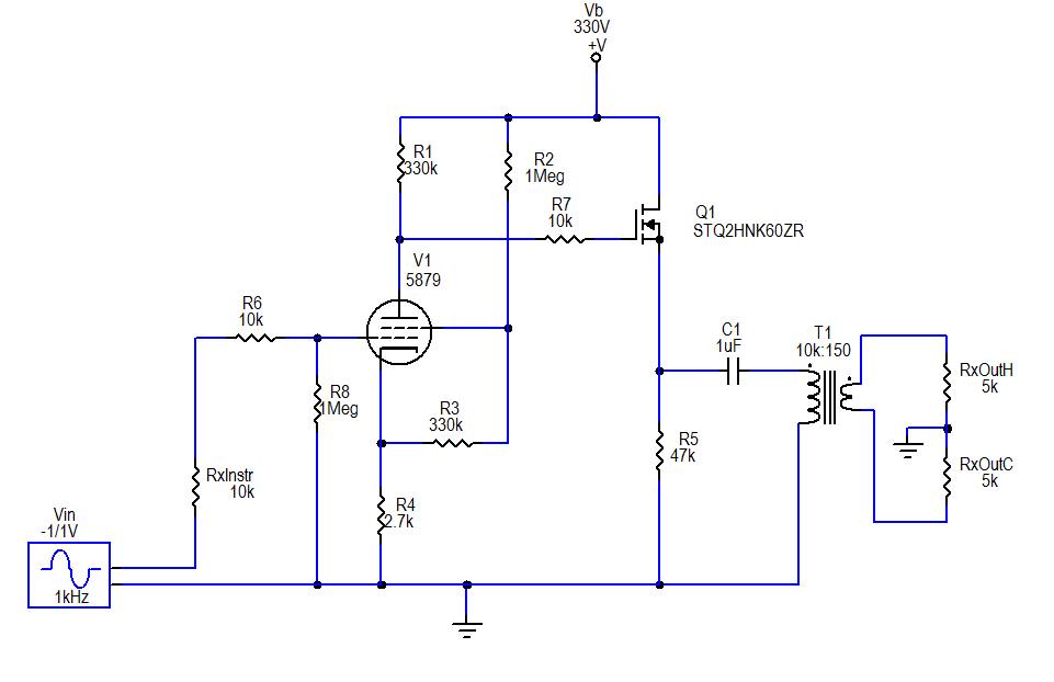
The Final Circuit

The final circuit
For the source follower stage, I selected The STQ2HNK60ZR-AP MOSFET. It is rated at 500V, is zener protected, and comes in a TO-92 package. I essentially kept with my previous plan for the rest of the circuit, except for a couple very minor changes: I added a 1 MΩ grid leak resistor on the pentode and 10 kΩ stopper resistors at the grid of the pentode and gate of the MOSFET; I reduced the source resistor value to 47 kΩ on the source follower section.

Although not depicted in the schematic, I added a textbook regulated DC heater supply, with a couple capacitors and a 7806 linear voltage regulator.  I decided to build this on a miniature terminal strip (0.25" spacing between lugs) that I had on hand.

The Chassis

Since the circuit is so much simpler than its original version, and so much more compact due to the change to a solid-state follower section, it became possible (with a little fussing) to take all the components inside the chassis box:

First steps in chassis modifications
First, I removed the tube socket turretboard and filter capacitor from the "top side" and plugged the holes with electrical box knockout plugs.

Then, I moved the input jack and neon power light off the "front" of the chassis and put them at the "back", i.e. the side that already had the power input, fuse, output connector and phase/lift switches. (I actually put in a different neon— I had bought a few smaller ones from the closing sale at my local Radio Shack.)

The pentode socket turretboard
Once those spaces were clear, I had room to move the filter choke into the area that had mostly been taken up with the old neon and wiring.

I modified the power supply board by removing the old "virtual center tap" heater resistors, adding a turret, and soldering on a monolithic bridge rectifier.  (The rectifier is over-rated for modest needs of the 150 mA, 6V heater, but I also had it on hand from Radio Shack).

The finished "gutshot"
I placed some adhesive bases for later mounting of the filter capacitor, moved the handle to the side, and plugged all the larger holes.  Not visible at the "front" side, I put some copper foil tape (with conductive adhesive) on the inside where all the jacks & potentiometers had been.

Outside back
To get the pentode inside the box, I made a little baby turretboard (about 1.8" × 3.4") mounted on a small section of aluminum angle.

The filter capacitor (with a few resistors directly attached) was attached to the adhesive bases with nylon cable ties.

Front view
The entire source follower circuit, including the 1μF coupling capacitor was assembled onto a miniature terminal strip similar to the one I used for the heater regulated supply.

It all fit, though the last stages of assembly were a bit cramped.  To finish it off, I designed a label and printed it on cardstock.  I put some adhesive aluminum tape on the back, and laminated it to the now blank "front" side of the chassis.  I decided to resurrect the "Lama Kazu" brand that I used for my first guitar amp project. I call this the LK5H, with the "5" referring to the pentode and the "H" for hybrid.

Results

The tone is essentially the same as it was in its earlier incarnations, but it's much cleaner.  Obviously hum has been reduced, down to about -60 dBu with input grounded, which is well below the level of hum picked up by any of my guitar pickups.  Most likely this hum is coupled in from the power transformers to the output transformer.  There's no way to get any mu-metal shielding inside this box, so this is how it will stay.

The noise floor looks to be on the order of -75 dBu, not exactly "audiophile", but good enough for an electric guitar.

Sunday, June 8, 2008

Amplifier Tweaks: Final Lama Kazu 8SE

The tweaks to a simple single-ended amp could be endless. I think this will be the last adjustment to the Lama Kazu 8SE, however. (Note: It wasn't! Some edits to this post were made in October.)


I decided to try a 12BZ7 in the second gain stage/cathode follower. Of course the bias had to be adjusted for that. Not knowing how exactly the 12BZ7 would act at clipping, I decided to add a small (3.9kΩ) grid stopper on the socket.

After using the amp for a couple months with the 12BZ7 installed, I ended up switching back to a 12AX7, but kept the hotter bias caused by the 1.5kΩ cathode resistor I put in for the 12BZ7.

I added a 560kΩ resistor in parallel with the drive potentiometer. This serves to cut the bass response as the drive is increased, and really reduces the muddiness at high gains.

I also decided to go over the whole thing and check my original calculations; it appears I chose the wrong tap on the output transformer when I built the thing. I changed it over from the 2.5kΩ to the 5kΩ tap. It's now actually capable of producing the 8-or-so watts of power I originally expected!

Now with the 'BZ7 there's not a "normal" tube in the whole setup!

Coming soon: Sound samples of everything...

Tuesday, July 17, 2007

First Amplifier Project, The Lama Kazu 8SE

It started as an attempt to create something like the Kalamazoo Model 1, but with more gain, better tone control and a master volume.

Summary
:
  • Single-ended, ~8W RMS (Clean); ~11W (Full distortion).
  • Preamp tubes: 2×ECC83. Power tube: 1×7591.
  • Speaker: Jensen C8R

Cabinet is FSC-certified pine, finished with Tried & True wood finish (hand-rubbed Linseed & Beeswax product). Grill cloth is Marshall "cane".


(Partly-visible bottom shielding is 6" wide aluminum flashing tacked to cabinet.)


Built in a Hammmond 13.5" × 5" × 2" aluminum chassis box. I forgot to take a picture of the circuit before final assembly, so here is an early image with just the power supply underway, and heatsink hemostats protecting a diode: