Showing posts with label MOSFET. Show all posts

Tuesday, March 23, 2021

Stompboxes: Revisiting the Stupid FET Trick

I was ordering some components for an upcoming stompbox project, so I decided to get enough extra to do some updates to my 2008 project, the Stupid FET Trick:
  • Add a 9V DC jack for adapter power.
  • Add a power light adjacent to the input jack to remind the user to unplug the input cord.
  • Add an "active" light next to the footswitch.
  • Add a graphic label.
I ended up using Valvewizard's MOSFET source-follower variant of the Millenium Bypass circuit for the "active" light.

Since I was adding the 9V jack, I also added a reverse-polarity diode, though it wasn't necessary to protect the effect circuit: The 2N5457 JFETs that make up the circuit have interchangeable source and drain, so reversing the polarity just turns every common-source gain stage into a common-drain buffer stage and vice-versa.  It won't actually work with power polarity reversed, but the JFETs won't be damaged.  The power LED can be damaged by reverse polarity so there is some purpose there.

Here's the schematic as it stands.  If you didn't read the original article, much of it was based on taking a typical tube amp approach, with component values adjusted for the lower voltages of a JFET circuit. A couple things were just outright mistakes, but I left them.

The graphic label (for the top surface only) was inkjet-printed onto vinyl label material, and features stylized versions of the original pictograms (☠💖🎶) for the knobs:

Aside from the mostly cosmetic and convenience changes, it's still the same guitar effect it was when I built it more than a decade ago:
  • It's not quite like any other distortion device I have.
  • It's still really noisy (mostly due to large-value resistors in the wrong places).
  • There's still DC current through the "Skull" and "Quaver" potentiometers, so they "scratch" when adjusted.
It also turns out that the 9V jack is not too useful: Since it's all Class-A gain stages, the power supply noise from a switching-mode "wall wart" supply that makes its way into the audio signal is just too much for even practice use.

I'll probably update this post with an audio recording soon, since I had never bothered to include one with the original design.

Here's what the simulated output is, with 1 kHz sine input and increasing "Skull" values:
Here's the effect of the "Heart" knob on frequency response:


Sunday, August 2, 2015

Re-imagining the 10LS/1LB Preamp, Part 3: The Lama Kazu LK5H

I built the 10LS/1LB preamp in 2008, and modified it a few times over the years. It has mostly been serving as a direct injection (DI) box for guitars. I recently undertook a major rework. See Part 1  and  Part 2 for more background.

The Final Circuit

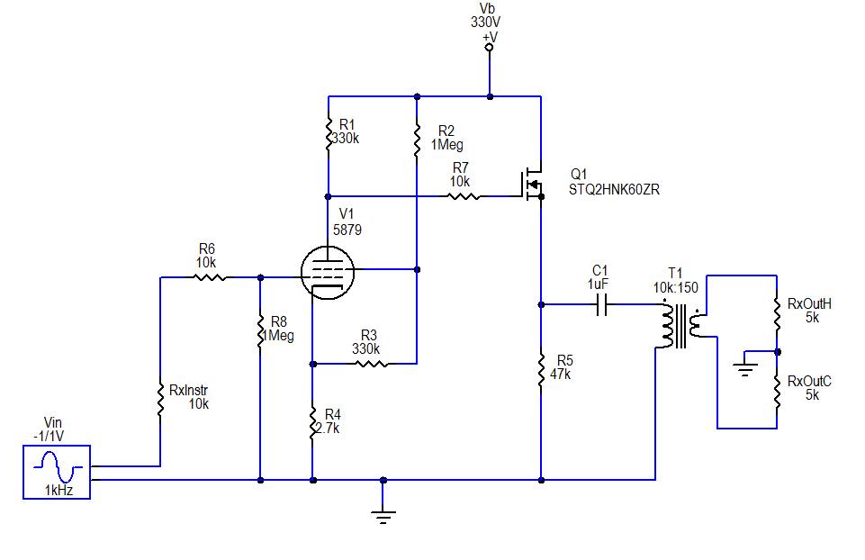
The final circuit
For the source follower stage, I selected The STQ2HNK60ZR-AP MOSFET. It is rated at 500V, is zener protected, and comes in a TO-92 package. I essentially kept with my previous plan for the rest of the circuit, except for a couple very minor changes: I added a 1 MΩ grid leak resistor on the pentode and 10 kΩ stopper resistors at the grid of the pentode and gate of the MOSFET; I reduced the source resistor value to 47 kΩ on the source follower section.

Although not depicted in the schematic, I added a textbook regulated DC heater supply, with a couple capacitors and a 7806 linear voltage regulator.  I decided to build this on a miniature terminal strip (0.25" spacing between lugs) that I had on hand.

The Chassis

Since the circuit is so much simpler than its original version, and so much more compact due to the change to a solid-state follower section, it became possible (with a little fussing) to take all the components inside the chassis box:

First steps in chassis modifications
First, I removed the tube socket turretboard and filter capacitor from the "top side" and plugged the holes with electrical box knockout plugs.

Then, I moved the input jack and neon power light off the "front" of the chassis and put them at the "back", i.e. the side that already had the power input, fuse, output connector and phase/lift switches. (I actually put in a different neon— I had bought a few smaller ones from the closing sale at my local Radio Shack.)

The pentode socket turretboard
Once those spaces were clear, I had room to move the filter choke into the area that had mostly been taken up with the old neon and wiring.

I modified the power supply board by removing the old "virtual center tap" heater resistors, adding a turret, and soldering on a monolithic bridge rectifier.  (The rectifier is over-rated for modest needs of the 150 mA, 6V heater, but I also had it on hand from Radio Shack).

The finished "gutshot"
I placed some adhesive bases for later mounting of the filter capacitor, moved the handle to the side, and plugged all the larger holes.  Not visible at the "front" side, I put some copper foil tape (with conductive adhesive) on the inside where all the jacks & potentiometers had been.

Outside back
To get the pentode inside the box, I made a little baby turretboard (about 1.8" × 3.4") mounted on a small section of aluminum angle.

The filter capacitor (with a few resistors directly attached) was attached to the adhesive bases with nylon cable ties.

Front view
The entire source follower circuit, including the 1μF coupling capacitor was assembled onto a miniature terminal strip similar to the one I used for the heater regulated supply.

It all fit, though the last stages of assembly were a bit cramped.  To finish it off, I designed a label and printed it on cardstock.  I put some adhesive aluminum tape on the back, and laminated it to the now blank "front" side of the chassis.  I decided to resurrect the "Lama Kazu" brand that I used for my first guitar amp project. I call this the LK5H, with the "5" referring to the pentode and the "H" for hybrid.

Results

The tone is essentially the same as it was in its earlier incarnations, but it's much cleaner.  Obviously hum has been reduced, down to about -60 dBu with input grounded, which is well below the level of hum picked up by any of my guitar pickups.  Most likely this hum is coupled in from the power transformers to the output transformer.  There's no way to get any mu-metal shielding inside this box, so this is how it will stay.

The noise floor looks to be on the order of -75 dBu, not exactly "audiophile", but good enough for an electric guitar.

Monday, July 20, 2015

Re-imagining the 10LS/1LB Preamp, Part 2

I built the 10LS/1LB preamp in 2008, and modified it a few times over the years. It has mostly been serving as a direct injection (DI) box for guitars. I recently undertook a major rework. See Part 1 for more background.

In-situ Modifications

Previous configuration.
For the first round of modifications, I kept everything in its original enclosure and on the turretboard.  For the first experiment, I removed the 12BZ7 dual triode and associated circuits, as well as the level control.

In-situ modifications
To replace the cathode follower stage, I put in a source follower with a LND150 MOSFET.  This might not be an ideal component for source follower service due to its relatively high RDS /low transconductance, but I had some on hand and it has a sufficient voltage rating (500V) for the application. I used the solder lugs from the 12BZ7 socket as a terminal strip for the MOSFET. The bias network on the 5879 was adjusted somewhat to allow the source follower to be center biased with DC coupling to the pentode stage.  Power supply and heater elevation circuits are omitted in the schematics for clarity.

Results

There was a decrease in hum when compared to the old circuit (-48dBu) and the tone seemed at least similar to the old circuit, but there were some new problems:
  • The gain was not quite enough. E.g.: Playing my Danelectro '63 baritone through it, I was peaking at about -15dBFS on my DAW.
  • Removing the 12BZ7's heater load sent the heater voltage excessively high-- about 8.4V AC! Remember that the heater transformer has a voltage regulation of 30% and was rated for 115V (i.e. Canadian) input, so a very high open circuit voltage happens with 120V on the primary.

Next steps

Next round of planned modifications.
The gain can be raised by increasing the anode resistor, and adjust the operating point to center bias it again. Of course there's a compromise: Increasing the anode resistor means reducing the idle current, which means lower transconductance and lower gain.  A 330k resistor seems to be about right.  The circuit will be something like the one here.

For the purposes of reducing hum, I was already contemplating a DC heater supply.  After seeing the overvoltage condition, it's obvious I need to do it regardless of the hum issue.  (Incidentally, I never measured the heater circuit voltage when the 12BZ7 was still in.  It was probably somewhat high, but not quite this high.)

I will probably do a by-the-book supply with a capacitor filter and linear regulator.  No reason to get fancy. A low-dropout regulator is not even going to be necessary with input voltage this high.

Since I'll need to add a heater power supply PCB, it's probably time to remove the turretboard and rewire the amplifier circuit.  The circuit is so simple, with so many components connected to the pentode socket, it makes sense to go point-to-point, on old fashioned terminal strips.  I might even be able to move everything (pentode, reservoir capacitor, and choke) inside the enclosure.

Sunday, July 12, 2015

Re-imagining the 10LS/1LB Preamp, Part 1

Front view with wooden cover


Back in 2008, I put together the 10LS/1LB Preamp. Since its original construction, I made a few on-the-fly modifications, and now after several years of occasional use, it's time to rework it to better meet the uses I have found for it, and to correct some of the shortcomings that have come to light.
Inside view

How It Turned Out

Since I didn't include many good photos in the original post, I've included some here.

I built a simple wooden cover (I can't quite call it a cabinet) to make it easier to carry.

Modifications have left some abandoned holes on the chassis. Only the largest (from the microphone input) was big enough to bother plugging.
Rear view with cover removed

Incidentally, the name "10LS/1LB" refers to the phrase "10 pounds of s**t in a 1-pound bag". The implication should be obvious from the inside view photo, especially when you consider that the small space at the lower left of the photo was once stuffed with a microphone input transformer and jack, feedthrough jack, and another potentiometer.

You can also see from the photos that lately it's been accumulating dust in a corner of the workshop area while waiting to be reborn.

Changes to the Circuit So Far

In addition to the adjustments described in my initial post on the device, I have made a few other tweaks over the years:
Amplifier board in its last incarnation

Top view with cover removed
The microphone input was essentially unusable, due to a combination of hum induced into the input transformer and noise at higher gain settings. I removed the transformer board, mic input jack and pad potentiometer to disable the feature entirely. It now functions only as an instrument preamp/DI box.
I rarely used the feed-through connection, so I removed that jack when I took out the microphone input.
Output transformer board
In an attempt to eliminate a noise source, I removed the 2 MΩ grid leak resistor from the input. This meant removing the input coupling capacitor (so that the instrument's pickup becomes the grid leak path) and trusting that there would be no DC on the instrument output. (The input jack is a shorting type, so the 5879's control grid is grounded with no input.)
Power supply board

The standby switch had an LED "on" indicator. The LED was powered through a half-wave rectifier which generated a lot of noise. I removed the standby switch circuit, and put in a simple neon lamp for power on indication.

In an attempt to reduce some of the hum from the pentode stage, I bypassed its cathode resistor with a large-value electrolytic capacitor I had on hand.  This did not make an appreciable impact on hum, so it was later removed.

A few minor adjustments were made to resistor values. I don't exactly remember all the changes or reasons.

Problems to Address

Hum
Final Schematic

Even with the heater elevation and reasonable (but not perfect) layout, 60 Hz hum is still objectionable. With the gain knob at minimum (showing only hum contribution through the triodes), the hum output is approximately -56 dBu. With gain knob at maximum (including hum contribution from pentode) it increases to -24 dBu. Maybe a DC heater supply for the pentode will be inevitable.

Noise

Yes, it's an open-loop tube amp with a pentode input, so I wasn't expecting it to be super clean, but the noise floor is a bit disappointing. Some of this can be addressed by changing the gain structure.

Gain

Since it's only used on instruments now, the gain (originally designed for mic level signals) is excessive and the triode gain stage is easily pushed into clipping. The level potentiometer is almost always used at the low end of its range, so there's probably 20dB excess gain. I suppose some negative feedback could be introduced, but I'd rather stick with my original intentions and the coloration of an open-loop pentode.

Supply Voltage

The high-voltage transformer was a bit oversized, and had a 30% voltage regulation, and therefore very high open-circuit voltage. I ended up with a supply voltage of 350V, a bit more than I should have used with the tubes I chose. At least it's easier to reduce voltage than to increase.

Plans for the Rework

Gain

The easiest way to drop the gain is to remove the triode gain stage.  Once that happens, the triode is only there for the cathode follower, which adds nothing sonically.  At that point, one may as well replace it with a MOSFET source follower.

One of the parameters of the original design was that swinging the cathode follower rail-to-rail would not generate an output signal in excess of input headroom on typical interfaces: A signal of approximately 140V, zero-to-peak (about 100 V RMS) through the 8:1 output transformer gives 12.5 V RMS out, or about 24 dBu.  +14 dB headroom above +10 dBu nominal is not unusual.

Since the pentode's output can't swing enough to cause an overload downstream, this also means we no longer need the level potentiometer!  The source follower stage can be DC coupled onto the pentode.

Power Supply

To drop the "B+", one easy fix is to change the power supply topology and make it a choke input filter rather than capacitor input.  Also, the dropping resistor between stages can be increased.

Before trying to add components for a DC heater supply to reduce hum, I will try the other fixes and see if the results are good.  By removing the triode, there may be a possibility of getting a regulated DC heater supply without changing the transformer.

Noise

Simplification of the topology to reduce gain will definitely help. Some of the resistors used were cheap carbon film (and even a carbon composition grid stopper) and can be replaced with better metal film.

Enclosure

Since there will only be one tube, and a simpler circuit, the pre-packaged turretboard can be removed and replaced, maybe with a PCB!

I should be able to fit everything inside the box.

In subsequent parts, I'll document my experiments and hopefully show a finished design!