Showing posts with label stompbox. Show all posts

Tuesday, March 23, 2021

Stompboxes: Revisiting the Stupid FET Trick

I was ordering some components for an upcoming stompbox project, so I decided to get enough extra to do some updates to my 2008 project, the Stupid FET Trick:
  • Add a 9V DC jack for adapter power.
  • Add a power light adjacent to the input jack to remind the user to unplug the input cord.
  • Add an "active" light next to the footswitch.
  • Add a graphic label.
I ended up using Valvewizard's MOSFET source-follower variant of the Millenium Bypass circuit for the "active" light.

Since I was adding the 9V jack, I also added a reverse-polarity diode, though it wasn't necessary to protect the effect circuit: The 2N5457 JFETs that make up the circuit have interchangeable source and drain, so reversing the polarity just turns every common-source gain stage into a common-drain buffer stage and vice-versa.  It won't actually work with power polarity reversed, but the JFETs won't be damaged.  The power LED can be damaged by reverse polarity so there is some purpose there.

Here's the schematic as it stands.  If you didn't read the original article, much of it was based on taking a typical tube amp approach, with component values adjusted for the lower voltages of a JFET circuit. A couple things were just outright mistakes, but I left them.

The graphic label (for the top surface only) was inkjet-printed onto vinyl label material, and features stylized versions of the original pictograms (☠šŸ’–šŸŽ¶) for the knobs:

Aside from the mostly cosmetic and convenience changes, it's still the same guitar effect it was when I built it more than a decade ago:
  • It's not quite like any other distortion device I have.
  • It's still really noisy (mostly due to large-value resistors in the wrong places).
  • There's still DC current through the "Skull" and "Quaver" potentiometers, so they "scratch" when adjusted.
It also turns out that the 9V jack is not too useful: Since it's all Class-A gain stages, the power supply noise from a switching-mode "wall wart" supply that makes its way into the audio signal is just too much for even practice use.

I'll probably update this post with an audio recording soon, since I had never bothered to include one with the original design.

Here's what the simulated output is, with 1 kHz sine input and increasing "Skull" values:
Here's the effect of the "Heart" knob on frequency response:


Monday, February 22, 2010

Microcontrollers, ho!

One way or another, the next major project will probably involve microcontrollers. A few possibilities:
  1. Reconfigurable tube guitar amplifier: An amplifier has a mutable topology that is be at least as flexible as a typical channel-switched amp, but with fewer signal-path components. The microcontroller is there to keep track of valid topological arrangements and operate relays and softswitches. It also mutes out switching sounds as appropriate and allows for timing sequences to prevent damage during switching. User favorites are assigned to a footswitch. It needs an entire amp designed and debugged with manual switching before the controller is brought into the mix.
  2. Digitally-controlled analog stompbox: The device is a distortion, filter & vibrato effect pedal. The signal path is analog, but reconfigurable in a similar way to the amplifier above. The MCU controls timing of the vibrato, which can be simple or complex, and set to an actual BPM tempo to match the music. In addition, an envelope sense circuit allows the vibrato to be synchronized to the incoming signal.
  3. Digital waveguide synthesizer: Based on the Karplus-Strong algorithm (US Pat 4,649,783), a standalone MIDI synthesizer module, though not necessarily simulating plucked or struck instruments. I'm thinking monophonic, bowed sounds with natural hammered-on slurs.
Projects 1 & 2 could use Arduino or one of the tiniest PICAXE controllers which are easy to program, but 3 would require a DSP, which could be integrated with the MCU (into a DSC). The usual microcontrollers don't have the RAM for a wavetable, and don't have the I/O speed to talk to a pro-audio-quality Digital-to-Analog converter. As far as I can tell, only PIC makes a DSC that is in-circuit programmable. I don't know if the PICAXE bootloader would work, or if another bootloader would be needed.

Saturday, May 17, 2008

Stompboxes I — The Buffalo Box B175

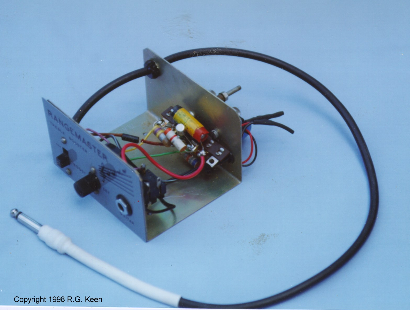
While performing inventory of my parts bins last fall, I came across a couple ancient-looking TO-1 metal cans. I have no recollection of their origin, but the leads were rather short, so I presume I cut them out of a junked radio or similar item, probably when I was a pre-teen. At first I presumed I acquired them at the same time, but it turns out they're from different manufacturers, so maybe not. One was labeled B175, the other was B186. A bit of searching showed they are both PNP germanium transistors intended for audio amplifier use. Word on the street was that should try one in a Rangemaster clone.

I breadboarded the crazy-simple circuit, and the B175 had a higher gain when plugged in, so I chose it for the finished project. I also added a bypass switch and an "anti-pop" 1MĪ© input resistor. I assembled it on a Radio Shack "Bug" PCB (276-159) and crammed it in a Bud econobox enclosure. A "vintage" knob controls the gain. The unadorned "natural aluminum" look I used with the LK8SE continues, and is even refined in my choice of functional legend on the unit.

I've never encountered a real Rangemaster, so I don't know if it sounds like one. It does work nicely with the LK8SE for "screaming solo" work. You need to crank up the bass control on the amp to get a crunchy sound, though.