
The Final Circuit
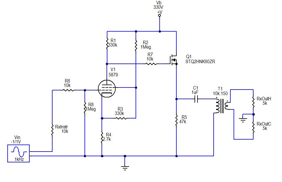 |
| The final circuit |
Although not depicted in the schematic, I added a textbook regulated DC heater supply, with a couple capacitors and a 7806 linear voltage regulator. I decided to build this on a miniature terminal strip (0.25" spacing between lugs) that I had on hand.
The Chassis
Since the circuit is so much simpler than its original version, and so much more compact due to the change to a solid-state follower section, it became possible (with a little fussing) to take all the components inside the chassis box: |
| First steps in chassis modifications |
Then, I moved the input jack and neon power light off the "front" of the chassis and put them at the "back", i.e. the side that already had the power input, fuse, output connector and phase/lift switches. (I actually put in a different neon— I had bought a few smaller ones from the closing sale at my local Radio Shack.)
 |
| The pentode socket turretboard |
I modified the power supply board by removing the old "virtual center tap" heater resistors, adding a turret, and soldering on a monolithic bridge rectifier. (The rectifier is over-rated for modest needs of the 150 mA, 6V heater, but I also had it on hand from Radio Shack).
 |
| The finished "gutshot" |
 |
| Outside back |
The filter capacitor (with a few resistors directly attached) was attached to the adhesive bases with nylon cable ties.
 |
| Front view |
It all fit, though the last stages of assembly were a bit cramped. To finish it off, I designed a label and printed it on cardstock. I put some adhesive aluminum tape on the back, and laminated it to the now blank "front" side of the chassis. I decided to resurrect the "Lama Kazu" brand that I used for my first guitar amp project. I call this the LK5H, with the "5" referring to the pentode and the "H" for hybrid.
Results
The tone is essentially the same as it was in its earlier incarnations, but it's much cleaner. Obviously hum has been reduced, down to about -60 dBu with input grounded, which is well below the level of hum picked up by any of my guitar pickups. Most likely this hum is coupled in from the power transformers to the output transformer. There's no way to get any mu-metal shielding inside this box, so this is how it will stay.
The noise floor looks to be on the order of -75 dBu, not exactly "audiophile", but good enough for an electric guitar.