Sunday, August 2, 2015

Re-imagining the 10LS/1LB Preamp, Part 3: The Lama Kazu LK5H

I built the 10LS/1LB preamp in 2008, and modified it a few times over the years. It has mostly been serving as a direct injection (DI) box for guitars. I recently undertook a major rework. See Part 1  and  Part 2 for more background.

The Final Circuit

The final circuit
For the source follower stage, I selected The STQ2HNK60ZR-AP MOSFET. It is rated at 500V, is zener protected, and comes in a TO-92 package. I essentially kept with my previous plan for the rest of the circuit, except for a couple very minor changes: I added a 1 MΩ grid leak resistor on the pentode and 10 kΩ stopper resistors at the grid of the pentode and gate of the MOSFET; I reduced the source resistor value to 47 kΩ on the source follower section.

Although not depicted in the schematic, I added a textbook regulated DC heater supply, with a couple capacitors and a 7806 linear voltage regulator.  I decided to build this on a miniature terminal strip (0.25" spacing between lugs) that I had on hand.

The Chassis

Since the circuit is so much simpler than its original version, and so much more compact due to the change to a solid-state follower section, it became possible (with a little fussing) to take all the components inside the chassis box:

First steps in chassis modifications
First, I removed the tube socket turretboard and filter capacitor from the "top side" and plugged the holes with electrical box knockout plugs.

Then, I moved the input jack and neon power light off the "front" of the chassis and put them at the "back", i.e. the side that already had the power input, fuse, output connector and phase/lift switches. (I actually put in a different neon— I had bought a few smaller ones from the closing sale at my local Radio Shack.)

The pentode socket turretboard
Once those spaces were clear, I had room to move the filter choke into the area that had mostly been taken up with the old neon and wiring.

I modified the power supply board by removing the old "virtual center tap" heater resistors, adding a turret, and soldering on a monolithic bridge rectifier.  (The rectifier is over-rated for modest needs of the 150 mA, 6V heater, but I also had it on hand from Radio Shack).

The finished "gutshot"
I placed some adhesive bases for later mounting of the filter capacitor, moved the handle to the side, and plugged all the larger holes.  Not visible at the "front" side, I put some copper foil tape (with conductive adhesive) on the inside where all the jacks & potentiometers had been.

Outside back
To get the pentode inside the box, I made a little baby turretboard (about 1.8" × 3.4") mounted on a small section of aluminum angle.

The filter capacitor (with a few resistors directly attached) was attached to the adhesive bases with nylon cable ties.

Front view
The entire source follower circuit, including the 1μF coupling capacitor was assembled onto a miniature terminal strip similar to the one I used for the heater regulated supply.

It all fit, though the last stages of assembly were a bit cramped.  To finish it off, I designed a label and printed it on cardstock.  I put some adhesive aluminum tape on the back, and laminated it to the now blank "front" side of the chassis.  I decided to resurrect the "Lama Kazu" brand that I used for my first guitar amp project. I call this the LK5H, with the "5" referring to the pentode and the "H" for hybrid.

Results

The tone is essentially the same as it was in its earlier incarnations, but it's much cleaner.  Obviously hum has been reduced, down to about -60 dBu with input grounded, which is well below the level of hum picked up by any of my guitar pickups.  Most likely this hum is coupled in from the power transformers to the output transformer.  There's no way to get any mu-metal shielding inside this box, so this is how it will stay.

The noise floor looks to be on the order of -75 dBu, not exactly "audiophile", but good enough for an electric guitar.

Monday, July 20, 2015

Re-imagining the 10LS/1LB Preamp, Part 2

I built the 10LS/1LB preamp in 2008, and modified it a few times over the years. It has mostly been serving as a direct injection (DI) box for guitars. I recently undertook a major rework. See Part 1 for more background.

In-situ Modifications

Previous configuration.
For the first round of modifications, I kept everything in its original enclosure and on the turretboard.  For the first experiment, I removed the 12BZ7 dual triode and associated circuits, as well as the level control.

In-situ modifications
To replace the cathode follower stage, I put in a source follower with a LND150 MOSFET.  This might not be an ideal component for source follower service due to its relatively high RDS /low transconductance, but I had some on hand and it has a sufficient voltage rating (500V) for the application. I used the solder lugs from the 12BZ7 socket as a terminal strip for the MOSFET. The bias network on the 5879 was adjusted somewhat to allow the source follower to be center biased with DC coupling to the pentode stage.  Power supply and heater elevation circuits are omitted in the schematics for clarity.

Results

There was a decrease in hum when compared to the old circuit (-48dBu) and the tone seemed at least similar to the old circuit, but there were some new problems:
  • The gain was not quite enough. E.g.: Playing my Danelectro '63 baritone through it, I was peaking at about -15dBFS on my DAW.
  • Removing the 12BZ7's heater load sent the heater voltage excessively high-- about 8.4V AC! Remember that the heater transformer has a voltage regulation of 30% and was rated for 115V (i.e. Canadian) input, so a very high open circuit voltage happens with 120V on the primary.

Next steps

Next round of planned modifications.
The gain can be raised by increasing the anode resistor, and adjust the operating point to center bias it again. Of course there's a compromise: Increasing the anode resistor means reducing the idle current, which means lower transconductance and lower gain.  A 330k resistor seems to be about right.  The circuit will be something like the one here.

For the purposes of reducing hum, I was already contemplating a DC heater supply.  After seeing the overvoltage condition, it's obvious I need to do it regardless of the hum issue.  (Incidentally, I never measured the heater circuit voltage when the 12BZ7 was still in.  It was probably somewhat high, but not quite this high.)

I will probably do a by-the-book supply with a capacitor filter and linear regulator.  No reason to get fancy. A low-dropout regulator is not even going to be necessary with input voltage this high.

Since I'll need to add a heater power supply PCB, it's probably time to remove the turretboard and rewire the amplifier circuit.  The circuit is so simple, with so many components connected to the pentode socket, it makes sense to go point-to-point, on old fashioned terminal strips.  I might even be able to move everything (pentode, reservoir capacitor, and choke) inside the enclosure.

Thursday, July 16, 2015

Discrete solid-state microphone preamp with low fixed gain

Proposed schematic
When I removed the microphone input from the 10LS/1LB Preamp, I was left with a spare Edcor MX8cs transformer.

When Radio Shack closed its retail stores and got out of the DIY component buisiness, I picked up a bunch of assorted "jellybean" transistors, as well as some 1N4733 5.1-volt zener diodes (along with a ton of other things).

All these solutions were in need of a problem, and I found it with my occasional need to record a drum kit on an audio interface with only two microphone preamps (The now-discontinued Echo AudioFire 4).

Even with a low-sensitivity microphone (like a SM57), a loud source (like a snare) will do just fine with the 18 dB of voltage gain inherent in the transformer.  All that's needed is to bring the impedance down (after it is increased by a factor of (8.2)² in the transformer) and drive a balanced line.

Here's the thought:

  • Drive the line from a two emitter followers using Sziklai pairs.  Biasing is through dc coupling to the transformer.
  • Use the 5.1V zener to derive a virtual ground point that's one VBE drop away from half of a 9V battery.
  • Input impedance can be selected with resistor R10.
More to come when I get around to building it...

Sunday, July 12, 2015

Re-imagining the 10LS/1LB Preamp, Part 1

Front view with wooden cover


Back in 2008, I put together the 10LS/1LB Preamp. Since its original construction, I made a few on-the-fly modifications, and now after several years of occasional use, it's time to rework it to better meet the uses I have found for it, and to correct some of the shortcomings that have come to light.
Inside view

How It Turned Out

Since I didn't include many good photos in the original post, I've included some here.

I built a simple wooden cover (I can't quite call it a cabinet) to make it easier to carry.

Modifications have left some abandoned holes on the chassis. Only the largest (from the microphone input) was big enough to bother plugging.
Rear view with cover removed

Incidentally, the name "10LS/1LB" refers to the phrase "10 pounds of s**t in a 1-pound bag". The implication should be obvious from the inside view photo, especially when you consider that the small space at the lower left of the photo was once stuffed with a microphone input transformer and jack, feedthrough jack, and another potentiometer.

You can also see from the photos that lately it's been accumulating dust in a corner of the workshop area while waiting to be reborn.

Changes to the Circuit So Far

In addition to the adjustments described in my initial post on the device, I have made a few other tweaks over the years:
Amplifier board in its last incarnation

Top view with cover removed
The microphone input was essentially unusable, due to a combination of hum induced into the input transformer and noise at higher gain settings. I removed the transformer board, mic input jack and pad potentiometer to disable the feature entirely. It now functions only as an instrument preamp/DI box.
I rarely used the feed-through connection, so I removed that jack when I took out the microphone input.
Output transformer board
In an attempt to eliminate a noise source, I removed the 2 MΩ grid leak resistor from the input. This meant removing the input coupling capacitor (so that the instrument's pickup becomes the grid leak path) and trusting that there would be no DC on the instrument output. (The input jack is a shorting type, so the 5879's control grid is grounded with no input.)
Power supply board

The standby switch had an LED "on" indicator. The LED was powered through a half-wave rectifier which generated a lot of noise. I removed the standby switch circuit, and put in a simple neon lamp for power on indication.

In an attempt to reduce some of the hum from the pentode stage, I bypassed its cathode resistor with a large-value electrolytic capacitor I had on hand.  This did not make an appreciable impact on hum, so it was later removed.

A few minor adjustments were made to resistor values. I don't exactly remember all the changes or reasons.

Problems to Address

Hum
Final Schematic

Even with the heater elevation and reasonable (but not perfect) layout, 60 Hz hum is still objectionable. With the gain knob at minimum (showing only hum contribution through the triodes), the hum output is approximately -56 dBu. With gain knob at maximum (including hum contribution from pentode) it increases to -24 dBu. Maybe a DC heater supply for the pentode will be inevitable.

Noise

Yes, it's an open-loop tube amp with a pentode input, so I wasn't expecting it to be super clean, but the noise floor is a bit disappointing. Some of this can be addressed by changing the gain structure.

Gain

Since it's only used on instruments now, the gain (originally designed for mic level signals) is excessive and the triode gain stage is easily pushed into clipping. The level potentiometer is almost always used at the low end of its range, so there's probably 20dB excess gain. I suppose some negative feedback could be introduced, but I'd rather stick with my original intentions and the coloration of an open-loop pentode.

Supply Voltage

The high-voltage transformer was a bit oversized, and had a 30% voltage regulation, and therefore very high open-circuit voltage. I ended up with a supply voltage of 350V, a bit more than I should have used with the tubes I chose. At least it's easier to reduce voltage than to increase.

Plans for the Rework

Gain

The easiest way to drop the gain is to remove the triode gain stage.  Once that happens, the triode is only there for the cathode follower, which adds nothing sonically.  At that point, one may as well replace it with a MOSFET source follower.

One of the parameters of the original design was that swinging the cathode follower rail-to-rail would not generate an output signal in excess of input headroom on typical interfaces: A signal of approximately 140V, zero-to-peak (about 100 V RMS) through the 8:1 output transformer gives 12.5 V RMS out, or about 24 dBu.  +14 dB headroom above +10 dBu nominal is not unusual.

Since the pentode's output can't swing enough to cause an overload downstream, this also means we no longer need the level potentiometer!  The source follower stage can be DC coupled onto the pentode.

Power Supply

To drop the "B+", one easy fix is to change the power supply topology and make it a choke input filter rather than capacitor input.  Also, the dropping resistor between stages can be increased.

Before trying to add components for a DC heater supply to reduce hum, I will try the other fixes and see if the results are good.  By removing the triode, there may be a possibility of getting a regulated DC heater supply without changing the transformer.

Noise

Simplification of the topology to reduce gain will definitely help. Some of the resistors used were cheap carbon film (and even a carbon composition grid stopper) and can be replaced with better metal film.

Enclosure

Since there will only be one tube, and a simpler circuit, the pre-packaged turretboard can be removed and replaced, maybe with a PCB!

I should be able to fit everything inside the box.

In subsequent parts, I'll document my experiments and hopefully show a finished design!

Sunday, May 31, 2015

An Op Amp & Diode Ladder Clipper

My recent series of posts about Fred Nachbaur's “Dogzilla” diode limiter was written because I was considering using a variant of that circuit in a forthcoming project. In the end, I realized Fred's circuit would not be suitable due to the high input voltage swing required to really make it effective.  I did come up with a soft clipper circuit using a diode ladder that would still work within a lower operating voltage range, which I will describe in this post.

Whereas the Dogzilla circuit took a big input signal and used the diode ladder to sequentially switch in a group of resistors in parallel on the bottom of an attenuator, I used the diode ladder in an operational amplifier's feedback loop to sequentially short out resistors in series, thus decreasing gain for greater output signals. Here's the basic configuration, with an ideal op amp:

When the output voltage is near 0, all four diode pairs are effectively open circuits, so the gain is determined by: A = - (R1 + R2 + R3 + R4) / Rin

As the output voltage increases in magnitude, the voltage across the largest resistor (in this case R4) will be the first to reach a diode forward drop, at which point D7 or D8 (depending on polarity) will turn on and the gain after that point is reduced to: A = - (R1 + R2 + R3) / Rin

This continues with further increases in output voltage, turning off the resistors from larger to smaller until the feedback resistance is effectively determined only by the series dynamic forward resistances of the diode string, about 2 kΩ under these conditions.

In practice, real diodes will switch on gradually, with all four transitions overlapping somewhat.  The transfer function looks like this:


Here are the currents flowing through diodes D2 (magenta), D4 (green), D6 (blue) and D8 (red) over the same range of input voltage.  (The odd-numbered diodes pick up the negative half of the input cycle):


Here are the voltages across R1 (magenta), R2 (red), R3 (blue) and R4 (green) for that same input:


Here is the output (green) in response to an increasing sine wave input (blue):


A few notes on this circuit (some may be obvious to you):

  1. To make a true soft clipper à la Nachbaur, there would be an additional resistor in the series string, with no corresponding diode pair bypassing it.  I omitted this resistor because I wanted the output to be strictly limited by the series voltage drop across all diodes.  This avoids the possibility of driving the op amp too close to its rails.  (Intentional clipping with diodes = good; unintentional clipping by the op amp = bad.)
  2. I chose an inverting amplifier configuration because the non-inverting arrangement must have a gain of at least 1.  I needed the circuit to act as an attenuator for the largest input signals to cause the hard limit behavior described above.
  3. You can shuffle the resistors around without changing the behavior.  The diodes will always turn on in descending order of their associated resistor value.
  4. The ratio of the gains from maximum to minimum (before hard clipping) must be greater than the number of diode pairs. To see why, consider the case with 4 resistors, with minimum resistance R1 and having a total series resistance of 4×R1 (thus setting the gain ratio to 4) the result is a degenerate case where all resistors are equal and all diodes in each direction turn on simultaneously. In order to have the diodes turn on squentially, the resistor values must increase (at least infinitessimally).
  5. Because the transfer function is symmetrical, only odd harmonic distortion is introduced. There are a few simple ways to introduce asymmetry, and therefore add some even harmonics.
I came up with a couple spreadsheets to help select resistors for the ladder.  Each starts with the same inputs: Total resistance of the string, input resistance, gain reduction ratio, and number of diode steps in the string. Here are links (on Google Sheets) to the spreadsheets; you can copy to your own Google Drive to edit:

  • Calculator 1 (quadratic gain change). This uses a linear change in individual resistors which leads to a quadratic gain reduction function by step.  This has a more gradual reduction from full gain (around the zero crossing), but a harder transition to full clipping at higher outputs.
  • Calculator 2 (geometric gain change). This uses a geometric change in individual resistors, which has a more quick reduction from highest gains , but a more gradual transition to full clipping.

Each has a minimum required gain ratio in order to get meaningful values for the resistors.  For Calculator 1, the ratio must be greater than the number of diode steps (see note 4 above).  For Calculator 2, the ratio must be greater than 2n-1.

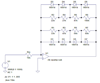
Here is the simplest way to introduce asymmetry: Use two different strings of resistors, each with diodes of only one polarity.  The effective total resistance (which sets maximum gain) is the parallel combination of both series strings:
The change in the transfer function is subtle:


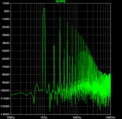
But a Fourier analysis (based here on 1 kHz sine input) shows some addition of even harmonics:


If you want to use fewer resistors, you could stagger the interconnections like this:


You could also modify any of the above with an unequal number of diodes in each polarity. This simple example:


Has a more obvious asymmetry in its transfer function:


And somewhat more pronounced even harmonics:


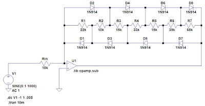
For my first test, I breadboarded the following variant of the circuit:


A few notes on this circuit:
  • I used a TL082CP dual op amp that I had on hand. It has a unity-gain bandwidth of 3 MHz and a slew rate of 13 V/µs.  Both of these end up being important, which is why I couldn't make use of the LM324 (1 MHz & 0.5 V/µs) that I also had on hand, which would have been better suited to single-ended battery power supply.
  • Resistor and capacitor values were chosen from what I had on hand.
  • The resistor/diode ladder was designed for 20:1 gain reduction before hard clipping. I used both calculator spreadsheets above, one for the positive half and one for the negative half. (Rather than using the resistor values directly, I had to compare the cumulative resistances and select incremental values to build up to the required totals.)
Here is a brief sound sample, playing a Yamaha RGZ211M (with various pickup & control settings) through the circuit, recorded direct to my audio interface:

Initial thoughts and impressions:
  • Since there was no tone shaping included in the circuit, it suffers from high-end fizz and the low end tends to swamp the distortion at high gain.  Not a surprise.  It probably needs a pre-emphasis/de-emphasis network to kill the bass before the distortion is applied, and a low pass to clean up the fizz.
  • Since there was no gain control, the guitar's volume must be used.  Over most of the adjustment range, the apparent loudness does not change much, only the color.  Only at the low end of the range is apparent volume affected.
  • It's noisy, especially with single-coil pickups.  Considering that it has a gain of about 46 dB for the quietest signals, I guess that's to be expected.  A noise gate is probably in order.


Sunday, May 3, 2015

The Nachbaur Diode Limiter, Part 3: Other variations

This post is part three in a series of three.
Part one discussed the basics.
Part two discussed transfer function shapes and resistor selection.

Listening Test

I ran a test of the Nachbaur Diode Limiter as a passive outboard effect.  The aux sends on my audio interface can drive about 8.18 V peak.  I breadboarded a 4-stage version like this:

Resistors were selected using my spreadsheet to have a final knee voltage of 8 V, and a final attenuation 10 (gain of 0.1).


Below are the audible results.  The program consists of a test tone and a DI-recording of my Danelectro 63 baritone guitar:
  1. 5 seconds of 1 kHz sine wave, increasing linearly in amplitude from 0 to full scale.
  2. A simple chord pattern.
  3. A simple single-note lead.
Each guitar section is normalized to full scale in order to just hit the last knee of the limiter.  The program is repeated for each of the following:
  1. Dry sound
  2. Through the limiter.
  3. Through a 160 Hz 1st-order highpass, normalized, and then through the limiter. (This was skipped for the 1 kHz test tone).
  4. Through the limiter, re-normalized, and then through the limiter again.
  5. Through a 160Hz 1st-order highpass, normalized, through the limiter, re-normalized, and then through the limiter again.  (This was skipped for the 1 kHz test tone).
Since the output impedance of the limiter is fairly high, I didn't use my interface's aux return, but rather the DI input. Here is the sound:

As you can see, it really doesn't sound like anything special in this setting.  I think it really needs a much hotter input than I could get out of my interface.

Anyway, here are a few thoughts on some changes you could make to the circuit without changing its topology completely, and while keeping it a passive attenuator:


Lower voltages with Schottky diodes

I might have tried this if I had any small signal Schottky diodes on hand.  Common ones like Vishay's BAT81S will have a forward voltage drop of about 300 mV under the conditions of this circuit.


Add a hard clipper to the last step

By eliminating the top resistor in the ladder, the last step becomes a "hard" clipper:

The transfer function looks like this (additional traces are the voltages at the lower diodes).  Note that the top diodes turn on gradually, so the last step (at about Vin=10 V) is only a "hard" knee in comparison to the earlier steps:


Split the diode ladder into two chains

With one string of diodes conducting on the positive signal voltages and one conducting on the negative, and different resistor selections in each, you can get an asymmetrical transfer function, which might be designed to mimic single-ended tube transfer function:


Break it up

You can save a little on headroom by putting the signal through a hard clipper, followed by enough make-up gain to push the hard clip limit beyond the last knee of the "Nachbaur".  The difference between this and simply including the hard clip in the diode ladder is that the hard clip input voltage is not constrained by the rest of the circuit, and can be selected independently by the gain structure.

You could also do more complicated multi-stage versions, with the extreme case being a single diode pair at each stage followed by makeup gain.


Closing

In the end I decided to save the Nachbaur and its variants for a future tube project.  There are other ways of making a soft clipper with a diode ladder that don't need the voltage swing.  More on that in another post. (Hint: feedback).

Monday, April 27, 2015

The Nachbaur Diode Limiter, Part 2: Selecting the resistors

This post is part two in a series of three.
Part one discussed the basics.
Part three discusses some other variations on the circuit.

It's not difficult to determine the resistances to use in the Nachbaur diode limiter circuit, starting with an arbitrary set of input voltages for each knee point in the curve, as long as the constraints discussed in part one are met.  The following spreadsheet (on Google Sheets) will perform the calculation: Nachbaur Limiter Calculator (voltage input)

If you select output voltages that don't meet the constraints mentioned in part one, you will get errors or odd outputs like negative-valued resistors.  You can save a copy of this sheet to your own Google Drive to edit.

Instead of using some arbitrary voltages, I wanted to fit a smooth curve with a fairly simple definition to the transfer function, and use that to set the voltages.  Mostly, I wanted to select:
  1. The input voltage corresponding to the last knee in the curve.
  2. The number of diodes in the ladder.
  3. The final gain (or limiting ratio).
A few notes on the math that comes out of this:
  • It's much easier to fit a curve to the inverse of the transfer function, since the diode voltage drops constrain the output voltage to known values.  This avoids having to derive inverse functions to perform the resistor selection.  Thus, this is the approach I took.
  • You can fit a parabola, Vin(v) = av² + bv + c, or a cubic function Vin(v) = av³ + bv² + cv + d, several different ways, but for a parabola, the final gain cannot be selected; for either polynomial, the curve meeting all the requirements is not guaranteed to be monotonic.  If you consider the first diode's part of the curve to be linear, you also have to constrain the slope of the polynomial at that point.
  • You can fit a simple power law curve Vin(v) = a (bv)p to the points.  In order for the ratio to increase, it requires p > 1.  You also can't constrain the slope at the end.    (If you choose the slope at the end, you can't constrain the input voltage at the final knee).
I also tried some experiments with combinations of linear and exponential/hyperbolic functions, but the curves tended to be too "hard", with impractically large resistance values at one end of the ladder,
and very small on the other.

The curve I ended up choosing as the "best" is a combination of a linear term and a power law scaled to fit.  The power law is then easily shaped by exponent (to get the right final ratio).  It's also guaranteed to be positive, monotonically increasing, and with a first derivative (limiter ratio) increasing from zero (as long as the exponent is greater than one), which is important for its smoothness when connected piecewise to Vin(v) = v (which describes the behavior before the first diode turns on).

The following spreadsheet will perform the calculation:  Nachbaur Limiter Calculator (power+linear)

Fitting a continuous function was not really necessary though, since we're approximating the diodes' behavior (diodes turn fully on at once, and have a fixed voltage drop) and we're only calculating the inverse transfer function at integer multiples of a diode forward voltage drop anyway.  I came up with this discrete option: If d represents a diode voltage drop, and p represents the final limiter ratio, we can calculate the increase in required input voltage at step N as d pi/N. The input voltage after step then is the sum:
...which doesn't seem so bad, until you try to solve for p, so that you can choose the final knee voltage.  In that case, the solution requires the Lambert W function, which spreadsheets don't seem to have and cannot be expressed in terms of elementary functions.  I guess you could just tinker with it until it works, or use your spreadsheet's goal seek function.

This spreadsheet will perform the calculation: Nachbaur Limiter Calculator (exponential ratio increase)

Interestingly, it turns out that the combination of resistors generated by this version resembles Fred's original resistor choices most closely. Just set your final limiting ratio to 9 to match his.  Also, when we get to Part three, we'll see that there's a way to tailor this version to fit the required voltages and ratio, while solving some other practical issues at the same time.

Although all the mathematics were fun, it turns out that for my planned application, there is a practical problem to using this circuit with any combination of resistors: An implementation with many diode steps requires a higher input voltage swing than I can manage. For the last limiter step to do its job, the input signal needs to go well beyond the highest knee voltage.  Some other tweaks are necessary.   But, if you're doing a tube circuit that can manage the voltage swing, you can still use it as-is.

Next post: Other variations.

Sunday, April 19, 2015

The Nachbaur Diode Limiter, Part 1: Basics

This post is part one in a series of three.
Part two discusses transfer function shapes and resistor selection.
Part three discusses some other variations on the circuit.

As part of a forthcoming project I'm going to call The Phantom Clipper, I revisited the limiter circuit included in the late Fred Nachbaur's "Dogzilla" amplifier.

In Fred's description of the circuit, he says he selected the resistors in the circuit "using a combination of simulated and empirical experiments to arrive at a smooth and easily-managed limiting curve."

In order to make use of it in a much different circuit, I wanted to analyze it a bit more closely, and come up with an algorithm to easily select all the resistors based on the desired transfer function.

Here's just the limiter portion of his circuit (inside the red outline):

It's a clever little circuit that effectively functions as a voltage divider attenuator, and uses a stack of anti-parallel small-signal diodes to switch additional resistors into the attenuator, increasing the attenuation of the divider as the input signal increases:
  • Around 0 volts in, none of the diodes conduct, so no current flows through any of the resistors, and it's as if the divider circuit were not there.
  • As the input voltage increases to reach the forward voltage drop of one diode, D27 switches on to make a voltage divider with R72 on top and R71 on bottom.  Gain = R71 / ( R71 + R72 ).
  • The voltage at the node between R71 and it's adjacent diodes D26 & D27 gets clamped at the diodes' forward drop, so further increases in voltage are attenuated by a divider with R72 on top (still), but R70 & R71 in parallel on the bottom. Gain = R71∥R70 / ( R71∥R70 + R72).
  • This continues until the output voltage reaches the total voltage drop of 5 diodes in series (about 3.5V), where the circuit functions as a divider with all five resistors R67 - R71 in parallel on the bottom.
  • Since the diodes are in anti-parallel pairs, the transfer function is symmetrical for the negative voltages.
Here's a graph of the positive half of the transfer function (green), with the voltage at each diode shown in the other colors.  You can see how the slope of the curve (gain) reduces as each diode switches in. You'll also notice the "knees" in the graph are not hard transitions, but a gradual bend towards the new slope.


So the circuit requires the transfer function to have a few properties:
  1. The transfer function must be monotonic.
  2. For input voltages up to ± one diode voltage drop, about ±0.7 volts, VOUT=VIN (gain = 1).
  3. Parallel resistances mean gain can only decrease for higher input voltage (it can't be an expander).
  4. Knee points (where the gain transitions) must occur at multiples of diode drop for output voltage.
  5. The input voltage where the last stage switches on is not easily determined directly from component values, but only by iterating through each step.
I created a spreadsheet (using Google Sheets) to calculate the approximate transfer function at each of the knee points, based on the resistors. Here it is: Nachbaur Limiter Calculator (resistor input).  You can make a copy to your own Google Drive to edit.

Next post: Selecting the resistors based on the desired transfer function.