Tuesday, March 23, 2021

Stompboxes: Revisiting the Stupid FET Trick

I was ordering some components for an upcoming stompbox project, so I decided to get enough extra to do some updates to my 2008 project, the Stupid FET Trick:
  • Add a 9V DC jack for adapter power.
  • Add a power light adjacent to the input jack to remind the user to unplug the input cord.
  • Add an "active" light next to the footswitch.
  • Add a graphic label.
I ended up using Valvewizard's MOSFET source-follower variant of the Millenium Bypass circuit for the "active" light.

Since I was adding the 9V jack, I also added a reverse-polarity diode, though it wasn't necessary to protect the effect circuit: The 2N5457 JFETs that make up the circuit have interchangeable source and drain, so reversing the polarity just turns every common-source gain stage into a common-drain buffer stage and vice-versa.  It won't actually work with power polarity reversed, but the JFETs won't be damaged.  The power LED can be damaged by reverse polarity so there is some purpose there.

Here's the schematic as it stands.  If you didn't read the original article, much of it was based on taking a typical tube amp approach, with component values adjusted for the lower voltages of a JFET circuit. A couple things were just outright mistakes, but I left them.

The graphic label (for the top surface only) was inkjet-printed onto vinyl label material, and features stylized versions of the original pictograms (☠💖🎶) for the knobs:

Aside from the mostly cosmetic and convenience changes, it's still the same guitar effect it was when I built it more than a decade ago:
  • It's not quite like any other distortion device I have.
  • It's still really noisy (mostly due to large-value resistors in the wrong places).
  • There's still DC current through the "Skull" and "Quaver" potentiometers, so they "scratch" when adjusted.
It also turns out that the 9V jack is not too useful: Since it's all Class-A gain stages, the power supply noise from a switching-mode "wall wart" supply that makes its way into the audio signal is just too much for even practice use.

I'll probably update this post with an audio recording soon, since I had never bothered to include one with the original design.

Here's what the simulated output is, with 1 kHz sine input and increasing "Skull" values:
Here's the effect of the "Heart" knob on frequency response:


Thursday, August 29, 2019

A Cosine-derived Well Temperament

Ever since I read about Brad Lehman's "Bach" tuning (some time in 2006), I have been interested in experimenting with unequal "well" temperaments for keyboard instruments.  But, it was only recently that I got a hardware synthesizer with reasonable capabilities for custom tunings.

While there seems to be insufficient proof that Lehman's tuning truly recreates anything used by J. S. Bach, it does adhere to the general goal that's implied in other historical well temperaments I've since read about:  A gradual change in "coloration" of the tuning as you go around the circle of fifths, with the most "just" major third (i.e. flat of equal-tempered) occurring in the key of C and the most "Pyhagorean" major third (i.e. sharp of ET) at the other side of the circle at F♯.  The width of the fifths in these temperaments appear to have been derived by trial and error to close the circle while achieving the desired thirds.  Precision was of course limited by the mechanical precision of the piano and the capabilities of the human tuner.

I decided to develop a well temperament mathematically, using a cosine function to adjust the width of the fifths gradually.  I used a spreadsheet to derive the thirds, and below are links (to Google Sheets) and a copy of the output, with two variations. The amount of stretch was chosen so that the widest fifths would be just (i.e. 3:2, about 701.955¢). For each of version, the flattest third (C-E) ends up about 7¢ sharp of just, and the sharpest third is about 20¢ sharp of just (but not quite Pythagorean).

Centered on C, with just fifths at C♯-G♯ and G♯-D♯:

-->
NoteIndexCosineFifthDegreeM3∆ Just
C00.7071698.5688400.000000C-E:393.2276786.913964
G10.9659698.044999698.568840G-B:394.1349977.821284
D20.9659698.044999196.613839D-F#:396.61383910.300125
A30.7071698.568840894.658838A-C#:400.00000013.686286
E40.2588699.476159393.227678E-G#:403.38616117.072447
B5-0.2588700.5238411092.703837B-D#:405.86500319.551289
F#6-0.7071701.431160593.227678F#-A#:406.77232220.458608
C#7-0.9659701.95500194.658838C#-F:405.86500319.551289
G#8-0.9659701.955001796.613839G#-C:403.38616117.072447
D#9-0.7071701.431160298.568840D#-G:400.00000013.686286
A#10-0.2588700.5238411000.000000A#-D:396.61383910.300125
F110.2588699.476159500.523841F-A:394.1349977.821284

Centered between C and G
, with a just fifth at G♯-D♯:

-->
NoteIndexCosineFifthDegreeM3∆ Just
C00.5000699.0225000.000000C-E:393.6813387.367624
G10.8660698.306920699.022500G-B:393.6813387.367624
D21.0000698.044999197.329419D-F#:395.3744189.060704
A30.8660698.306920895.374418A-C#:398.30692011.993206
E40.5000699.022500393.681338E-G#:401.69308015.379367
B50.0000700.0000001092.703837B-D#:404.62558218.311868
F#6-0.5000700.977500592.703837F#-A#:406.31866220.004948
C#7-0.8660701.69308093.681338C#-F:406.31866220.004948
G#8-1.0000701.955001795.374418G#-C:404.62558218.311868
D#9-0.8660701.693080297.329419D#-G:401.69308015.379367
A#10-0.5000700.977500999.022500A#-D:398.30692011.993206
F110.0000700.000000500.000000F-A:395.3744189.060704

Here are the tunings in Scala format if you would like to use them:

! Cosine C Well.scl
!
C-Centered Cosine Well
 12
!
 94.65884
 196.61384
 298.56884
 393.22768
 500.52384
 593.22768
 698.56884
 796.61384
 894.65884
 1000.00000
 1092.70384
 2/1

! Cosine CG Well.scl
!
C/G-Centered Cosine Well
 12
!
 93.68134
 197.32942
 297.32942
 393.68134
 500.00000
 592.70384
 699.02250
 795.37442
 895.37442
 999.02250
 1092.70384
 2/1

Incidentally, these are rather nice-looking when viewed through Scala's temperament radar:

C-Centered Cosine Well Temperament - Radar

C/G-Centered Cosine Well Temperament - Radar


Monday, September 3, 2018

Stopping the Squeaks on a Burghardt Scissor-Jack Piano Bench

With a good piano, decent microphones, a [Really] nice preamp, and a not-bad A/D converter, you'd hope that playing ability would be the only thing to prevent a good piano recording in a home studio…  Then you play back to find that the squeaking piano bench is louder than the all but the loudest passages. Judging from the numerous discussion threads on piano-related online forums, I presume it's a common problem.  I discovered a relatively simple solution that might be helpful to others.

My bench is an adjustable Burghardt with a "scissor jack" style lifting mechanism, but my squeak solution should be applicable to some other types of benches.


I searched online for some solutions:

  • "Frequently tightening bolted joints." – Considering the bench came with its own wrench, the manufacturer must have been expecting this approach, but eventually it stops working.  It also only works for squeaks between the legs and apron board.
  • "Ensuring the bench is upright, on a level surface before tightening leg bolts." – I loosened the leg bolts and tried, but there was no difference.
  • "Putting Vaseline (or other lubricants) in wood-to-wood joints between apron and legs." – It seemed like this would be bad for the wood finish.
  • "WD40 at various locations." – Also bad for the wood finish, and not a good long term solution.

As I was reading these aloud, my wife suggested inserting a piece of fabric into the joints, and offered a scrap of nylon. That's when I remembered I had a partial roll of Rockler "Nylo-Tape" from a furniture project.  Nylo-tape is adhesive-backed nylon tape. I had 3/4" wide × 10 mil thick on hand, which worked just right.

First, I removed the legs (keeping track of which goes where!) and applied short pieces of Nylo-tape to the ends of each apron board, where they bear against the legs.

Then I applied long strips of Nylo-tape between the the lifting mechanism and the two wooden frames.  I just cut them a little longer than needed, marked the backing with the position of each hole, and then used a standard handheld office paper punch to make holes for the screws in each strip of tape.  (I actually removed each frame from the mechanism in turn, rather than all at once, to make it easier to put back in the right orientation.)


I did not apply any Nylo-tape between the corner brackets and the apron, partly because the squeaking seemed to stop after the first round of fixes, and partly because I ran out of Nylo-tape.  If new squeaks develop there, I may have to apply some later:

Tuesday, January 26, 2016

The Tube Technology behind Ghost in the Museum

A brief update because Ghost in the Museum by Diane Marie Kloba was released today, and I used some of my homebrew gear in recording my parts for the album:

My BoxHead amplifier was used for the baritone guitar part that's featured throughout the track "Rescued".  It was close-mic'd with an Electro-Voice N/D-468 dynamic, one of my favorite all purpose dynamics. The guitar itself is the Danelectro 63 that I upgraded a while ago:


My re-worked LK5H DI Box was used for the baritone guitar (including EBow passage) on "Only Summer Brings":


The LK5H was also used for the parallel EBow guitar parts on "A Thousand Pretty Strings". I really liked using it on the EBow because it simplified recording, and because the guitars have such a "hot" signal level when driven by the EBow that the pentode input on the LK5H gets some nice clipping character:


Bonus track: This was released on Soundcloud last year and is not part of any album. I played the lead guitar part on "Aching" through my Buffalo Box B175 and my Lama Kazu 8SE Amplifier.  I recorded with a Cascade Vin-Jet ribbon mic.

Sunday, August 2, 2015

Re-imagining the 10LS/1LB Preamp, Part 3: The Lama Kazu LK5H

I built the 10LS/1LB preamp in 2008, and modified it a few times over the years. It has mostly been serving as a direct injection (DI) box for guitars. I recently undertook a major rework. See Part 1  and  Part 2 for more background.

The Final Circuit

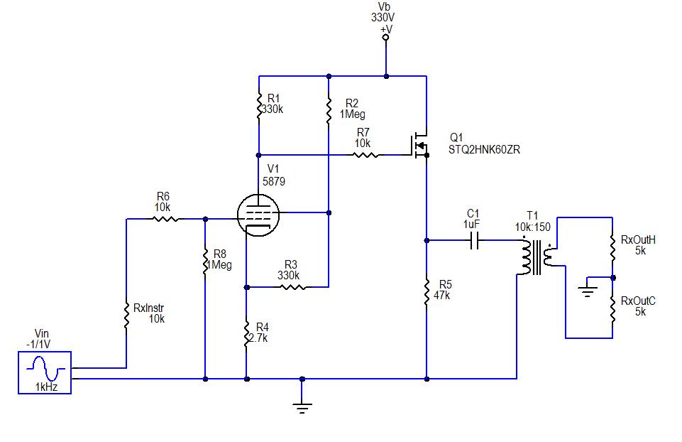
The final circuit
For the source follower stage, I selected The STQ2HNK60ZR-AP MOSFET. It is rated at 500V, is zener protected, and comes in a TO-92 package. I essentially kept with my previous plan for the rest of the circuit, except for a couple very minor changes: I added a 1 MΩ grid leak resistor on the pentode and 10 kΩ stopper resistors at the grid of the pentode and gate of the MOSFET; I reduced the source resistor value to 47 kΩ on the source follower section.

Although not depicted in the schematic, I added a textbook regulated DC heater supply, with a couple capacitors and a 7806 linear voltage regulator.  I decided to build this on a miniature terminal strip (0.25" spacing between lugs) that I had on hand.

The Chassis

Since the circuit is so much simpler than its original version, and so much more compact due to the change to a solid-state follower section, it became possible (with a little fussing) to take all the components inside the chassis box:

First steps in chassis modifications
First, I removed the tube socket turretboard and filter capacitor from the "top side" and plugged the holes with electrical box knockout plugs.

Then, I moved the input jack and neon power light off the "front" of the chassis and put them at the "back", i.e. the side that already had the power input, fuse, output connector and phase/lift switches. (I actually put in a different neon— I had bought a few smaller ones from the closing sale at my local Radio Shack.)

The pentode socket turretboard
Once those spaces were clear, I had room to move the filter choke into the area that had mostly been taken up with the old neon and wiring.

I modified the power supply board by removing the old "virtual center tap" heater resistors, adding a turret, and soldering on a monolithic bridge rectifier.  (The rectifier is over-rated for modest needs of the 150 mA, 6V heater, but I also had it on hand from Radio Shack).

The finished "gutshot"
I placed some adhesive bases for later mounting of the filter capacitor, moved the handle to the side, and plugged all the larger holes.  Not visible at the "front" side, I put some copper foil tape (with conductive adhesive) on the inside where all the jacks & potentiometers had been.

Outside back
To get the pentode inside the box, I made a little baby turretboard (about 1.8" × 3.4") mounted on a small section of aluminum angle.

The filter capacitor (with a few resistors directly attached) was attached to the adhesive bases with nylon cable ties.

Front view
The entire source follower circuit, including the 1μF coupling capacitor was assembled onto a miniature terminal strip similar to the one I used for the heater regulated supply.

It all fit, though the last stages of assembly were a bit cramped.  To finish it off, I designed a label and printed it on cardstock.  I put some adhesive aluminum tape on the back, and laminated it to the now blank "front" side of the chassis.  I decided to resurrect the "Lama Kazu" brand that I used for my first guitar amp project. I call this the LK5H, with the "5" referring to the pentode and the "H" for hybrid.

Results

The tone is essentially the same as it was in its earlier incarnations, but it's much cleaner.  Obviously hum has been reduced, down to about -60 dBu with input grounded, which is well below the level of hum picked up by any of my guitar pickups.  Most likely this hum is coupled in from the power transformers to the output transformer.  There's no way to get any mu-metal shielding inside this box, so this is how it will stay.

The noise floor looks to be on the order of -75 dBu, not exactly "audiophile", but good enough for an electric guitar.